Today you will program the rules for a tiny intersection. Three LEDs will act like traffic lights: red, yellow, and green. But the real new skill is not just adding more lights—it is learning how to organize code so a program stays understandable as it grows.
Instead of writing one huge pile of instructions, you will create small named jobs called functions. Then, for your independent challenge, you will add a flashing crosswalk phase with a for loop.
At a glance
| Age range | 10–13 |
|---|---|
| Estimated time | 60–80 minutes |
| Difficulty | Beginner-plus |
| Parent involvement | Light after the first LED is checked |
| Major concepts | Multiple outputs, timing, functions, sequence, for loops |
What you will learn
- How to repeat the safe LED-and-resistor wiring pattern three times.
- How one Arduino can control several outputs on different pins.
- How a program can run a timed sequence.
- What a function is and why a name such as
showGreen()is useful. - How a
forloop repeats a small job a chosen number of times. - How to plan a rule in plain English before changing code.
Before you begin
Complete Lesson 2: Build a Push-to-Shine Arduino Light first. You should already know that every LED needs its own resistor, that the LED’s long leg is the positive side, and that a breadboard’s center trench does not connect across.
Your Uno should still appear as Arduino Uno in Arduino IDE. If the computer cannot find the board, unplug all breadboard wires and run the built-in Blink sketch from Lesson 1 before troubleshooting a three-LED circuit.
For the first 10 minutes, you may rehearse the three LEDs in Tinkercad Circuits. The simulator is useful for seeing a repeated wiring pattern. Then move to the real Uno—the physical build is where you learn to trace wires and debug.
Keep the Debugging Ladder nearby. When a three-light project acts strangely, test one color and one pin at a time.
What you need
Required components
| Quantity | Item | Compatible substitute |
|---|---|---|
| 1 | Arduino Uno from the Arduino Student Kit | Genuine Uno R3 or Uno R3 SMD |
| 1 | Solderless breadboard | Standard half-size breadboard |
| 1 each | Red, yellow, and green LEDs | Any three different-color ordinary LEDs |
| 3 | 220 Ω resistors | 330 Ω or 560 Ω resistors; one per LED |
| 7–9 | Male-to-male jumper wires | Solid-core breadboard wires |
| 1 | USB-A to USB-B data cable | Arduino-branded USB-A-to-B data cable |
Optional components
- Cardboard, paper, tape, and markers for a traffic-light housing or small intersection.
- A maker notebook and pencil.
- A fourth LED plus one 220 Ω resistor, if you want a separate pedestrian light later. It is not needed for the required challenge.
Tools
None. This project is solderless.
Computer/software requirements
- Arduino IDE 2 with Arduino Uno and its port selected.
- A Mac running macOS 10.15 or later, or Windows 10 64-bit or newer.
- Optional: a free Autodesk account and a current browser for Tinkercad.
Safety and setup notes
- Unplug the USB cable before adding or moving wires.
- Every LED gets its own resistor. Do not share one resistor between LEDs and never connect an LED straight from an Arduino pin to ground.
- Keep all three LED short legs on the same ground rail. This makes the circuit easier to read and test.
- Use only USB power for this project. Do not add a battery or wall power.
- The adult should step in if a component becomes warm, the board resets repeatedly, or a wire may be shorting a pin directly to ground. Otherwise, let the student build one LED pattern at a time.
Build overview
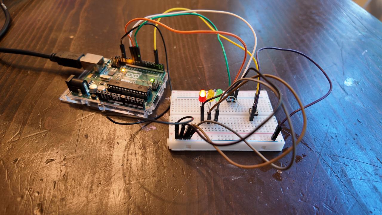
This program controls three outputs:
Arduino D8 → red LED
Arduino D9 → yellow LED
Arduino D10 → green LED
The loop() section will read like a short traffic plan: red, red-and-yellow, green, yellow, then repeat. The functions below loop() are named toolboxes. When the program sees showGreen(), it goes to that toolbox, turns on the correct light, and returns to the plan.
The Arduino is not deciding based on a sensor yet. It is following a timed sequence. Next lessons will combine these outputs with real inputs.
Step-by-step build instructions
Step 1: Set up one shared ground rail
- Place the breadboard with the long center trench running left to right.
- Use a black jumper to connect an Arduino GND pin to one long breadboard rail. This is your shared ground rail.
- Choose a clear vertical arrangement for the LEDs: red at the top, yellow in the middle, green at the bottom.
Checkpoint: point to the shared ground rail and explain why all three LEDs can return electricity to the same place.
Step 2: Place the three LEDs and their resistors
For each LED, place its two legs in different connected rows in the main breadboard area. Keep the colors in the chosen traffic-light order.
- Connect each LED’s short leg (or flat-side leg) to the shared ground rail with a short black jumper.
- Put one end of a 220 Ω resistor in the row with the long leg of the red LED. Put the resistor’s other end in a new, empty row.
- Repeat the same resistor pattern for the yellow and green LEDs. Each resistor must be separate.
Checkpoint: trace each color from its long LED leg through its own resistor. If two LED legs share one connected row, move one before continuing.
Step 3: Connect the Arduino output pins
Connect a separate jumper from each Arduino pin to the free end of that LED’s resistor.
| Arduino pin | LED color | Complete path |
|---|---|---|
| D8 | Red | D8 → resistor → red LED long leg → red LED short leg → ground |
| D9 | Yellow | D9 → resistor → yellow LED long leg → yellow LED short leg → ground |
| D10 | Green | D10 → resistor → green LED long leg → green LED short leg → ground |
Use a red wire for D8 and a green wire for D10 if you have them. The wire color is not electricity, but it makes your future self a better debugger.
Checkpoint: say the matching pin number and color three times: “D8 red, D9 yellow, D10 green.” Then compare the wiring table to the actual breadboard.
Step 4: Upload the traffic-signal program
- Connect the Uno to the computer with the USB data cable.
- Open Arduino IDE and confirm Arduino Uno and its port are selected.
- Create a new sketch, remove any starter text, and paste or type the complete code below.
- Click Verify. Fix the first error before uploading.
- Click Upload and wait for Done uploading.
Checkpoint: the signal should show red for three seconds, red and yellow for one second, green for three seconds, and yellow for one second before repeating.
Step 5: Test one color at a time
Watch two complete cycles. As each phase appears, point to the named function that should be running.
- Red phase: only red is on.
- Red-and-yellow phase: red and yellow are on together.
- Green phase: only green is on.
- Yellow phase: only yellow is on.
If a color is wrong, do not rewrite the program. Trace that color’s one path from the listed Arduino pin through its resistor and LED to ground.
Code
const int RED_LED_PIN = 8;
const int YELLOW_LED_PIN = 9;
const int GREEN_LED_PIN = 10;

void setup() {
  pinMode(RED_LED_PIN, OUTPUT);
  pinMode(YELLOW_LED_PIN, OUTPUT);
  pinMode(GREEN_LED_PIN, OUTPUT);

  allLightsOff();
}

void loop() {
  showRed();
  delay(3000);

  showRedAndYellow();
  delay(1000);

  showGreen();
  delay(3000);

  showYellow();
  delay(1000);
}

void allLightsOff() {
  digitalWrite(RED_LED_PIN, LOW);
  digitalWrite(YELLOW_LED_PIN, LOW);
  digitalWrite(GREEN_LED_PIN, LOW);
}

void showRed() {
  allLightsOff();
  digitalWrite(RED_LED_PIN, HIGH);
}

void showRedAndYellow() {
  allLightsOff();
  digitalWrite(RED_LED_PIN, HIGH);
  digitalWrite(YELLOW_LED_PIN, HIGH);
}

void showGreen() {
  allLightsOff();
  digitalWrite(GREEN_LED_PIN, HIGH);
}

void showYellow() {
  allLightsOff();
  digitalWrite(YELLOW_LED_PIN, HIGH);
}
What the important code means
- Variables:
RED_LED_PIN,YELLOW_LED_PIN, andGREEN_LED_PINare clear names for the real Arduino pins. Clear names help you avoid mixing up D8, D9, and D10. setup(): this runs once when the board starts. It makes all three pins outputs and then turns all three lights off for a clean start.loop(): this is the traffic plan. It calls one state, waits, calls the next state, waits, and then repeats forever.- Inputs and outputs: this lesson has three outputs—the LEDs—and no electronic input yet. The code’s timing is the “rule maker.”
- Functions:
showGreen()is a named mini-program. Instead of copying threedigitalWrite()lines every time the signal needs green,loop()can call the function by name. allLightsOff(): each light function begins by turning every light off. That is why the program does not accidentally leave an old color on.
Make it work
Your first version works when all of these are true:
- Arduino IDE says Done uploading.
- Red appears by itself for about three seconds.
- Red and yellow appear together for about one second.
- Green appears by itself for about three seconds.
- Yellow appears by itself for about one second.
- The sequence repeats without a light staying on by accident.
- You can explain why
showGreen()is easier to read than a random group of threedigitalWrite()lines in the middle ofloop().
Understand it
- Why does each LED need its own resistor even though all three use the same ground rail?
- What would happen if
showGreen()did not callallLightsOff()first? - What is the difference between the job of
setup()and the job ofloop()? - Predict what would happen if you changed
delay(3000)aftershowGreen()todelay(500). - Why is
showRedAndYellow()a useful function name instead of simply writing the twodigitalWrite()lines insideloop()?
Required “change it” challenge
Desired outcome: add a school-crosswalk phase after the yellow phase. During that phase, the red traffic light stays on while the green LED acts as a pretend pedestrian signal and flashes exactly three times. Then the normal cycle begins again with red.
Constraints: use a for loop instead of copying the same flash code three times; keep red on through the whole crosswalk phase; do not add parts; use a function with a clear name such as showCrosswalk().
Hints:
- Write the rule in plain English first: red on; green on/off three times; red remains on; return to normal red.
- Put the repeated green on/off instructions inside
for (int flash = 0; flash < 3; flash++) { ... }. The number3is the number of flashes. - Make a new function below
showYellow(). At the beginning, turn yellow off and turn red on. Inside the loop, turn green on, wait a short time, turn green off, wait a short time. Call your new function inloop()after the yellow delay.
Parent guidance: allow the student to draw the pattern and try the for loop before explaining every symbol. A healthy struggle is deciding what repeats and what stays on. If he is stuck, ask, “Which two lines happen three times?” Do not write the finished function for him. Step in if the loop runs forever, if the student cannot identify the line that changes the counter, or if 15–20 minutes pass without a new small test.
Optional enhancements
Try this
Change the length of one phase to fit a quiet neighborhood or a busy downtown. Before uploading, write which phase will become longer or shorter and why.
Challenge
Reuse the button from Lesson 2 as a crosswalk-request button. Pressing it should not instantly change the light; first write a rule for when the request is safe to honor. Make a drawing and a plan before you add wires or code.
Stretch
Build a cardboard intersection with a road, a traffic-light housing, and a small sign explaining your programmed traffic rules. Ask someone to watch the cycle and tell you whether it seems safe and understandable.
Debugging guide
| What you notice | Likely cause | Smallest next diagnostic step |
|---|---|---|
| The Uno is not detected or has no green power LED | Computer/cable problem, not the traffic circuit | Unplug all breadboard wires and test the built-in Blink sketch with the supplied data cable. |
| One color never lights | That LED is reversed, the wrong pin is used, or its resistor path is open | Trace just that color using the D8/D9/D10 table. Check long leg → resistor → Arduino pin, short leg → ground. |
| The wrong color lights in a phase | The pin wires are mixed up | Compare one wire at a time: D8 red, D9 yellow, D10 green. Do not change code until the physical map matches. |
| Two lights are always on | Two LED legs share a breadboard row, or allLightsOff() was changed | First inspect whether neighboring LED legs share a connected row; then compare the allLightsOff() function to the lesson code. |
| All LEDs are dark | The ground rail is not connected to Arduino GND, LEDs are all reversed, or upload failed | Confirm the black GND wire, then test red LED’s one path before looking at the other two. |
| An LED is dim or warm | Resistor is missing/wrong, or a short exists | Unplug immediately. Confirm each LED has its own 220 Ω/330 Ω/560 Ω resistor in series. |
| The code does not compile after the challenge | Missing brace, semicolon, or flash++ in the for loop | Read the first error line, then count the opening/closing braces and check the loop counter. |
| The crosswalk keeps flashing forever | The loop condition or counter update is wrong | Check for all three pieces: start at 0, test < 3, and add flash++. |
If a small test does not reveal the issue, use the Debugging Ladder and restore the last known-good main traffic-signal code before trying the crosswalk change again.
Recap
You used three separate Arduino outputs to make a timed traffic signal. More importantly, you organized your code with named functions so the main plan stayed easy to read. In the crosswalk challenge, you practiced using a for loop to repeat a short pattern without copying it again and again.
Show what you learned
Write or tell your parent:
- What did each traffic-light function do?
- What did you change in the crosswalk phase, and how many times should it flash?
- What failed, if anything, and what was your smallest debugging test?
- Why is a
forloop better than copying the green on/off lines three times?
In your maker notebook, draw your full signal cycle as a timeline. Label each phase and its timing. Take a direct overhead photo of the finished breadboard before moving any wires.
What’s next
Next, your Arduino will gain a voice. In Lesson 4, you will connect a piezo buzzer and use buttons to trigger different sound effects. The functions you learned here will make it easier to organize those sounds. Continue to Lesson 4: Program a Sound-Effect Machine.
NEXT · LESSON 04Lesson 4: Program a Sound-Effect Machine
Parent guide
Prepare in advance
- Confirm the Uno uploads the Lesson 1 Blink sketch before setting out new parts.
- Set out three LEDs, three resistors, the breadboard, jumpers, Uno, cable, and notebook. Keep cardboard aside until the main circuit works.
- Open or print the labeled breadboard diagram. Have the student say the pin/color map before wiring.
- Decide that the first response to a wrong light will be to trace one color—not to rebuild all three.
Let the child work independently when
- placing each LED and identifying its long/short leg;
- repeating the one-LED wiring pattern for each color;
- matching pin names to LED colors in the code;
- predicting timing changes; and
- drawing the crosswalk rule and attempting the
forloop.
Resist taking over when
- the first physical layout is not perfectly straight or pretty;
- he confuses two pin colors but can compare the map and find the mismatch;
- the main code feels longer than Lesson 2 and he needs time to find the functions; or
- he needs to make one small syntax correction after reading the error.
Step in when
- any LED/resistor becomes warm, a resistor is missing, or a direct short is suspected;
- the board connection fails before the circuit can be tested;
- he has traced the same light carefully and made a small test but has no next hypothesis; or
- the crosswalk loop runs indefinitely and he cannot recover the known-good version. Save the working main sketch before attempting the challenge.
Simple understanding-based assessment
Ask the student to point to each LED’s output pin, then ask: “Which function makes the green phase? Why does it call allLightsOff() first? Which two lines repeat in your crosswalk loop?” Award one point each for a working/tested build, a correct explanation, a deliberate crosswalk change, and a useful debugging/notebook note. A working traffic light without a clear explanation is not a complete success.
Further resource: Arduino LED Bar Graph example