MECHANICAL ENGINEERING & MACHINES · LEVEL 1 · LESSON 1
Build a Maker Parts Tray: The 3 mm Challenge
Can you turn one flat card into a useful tray—and land within 3 mm?
Your mission
Can you turn one flat card into a useful tray—and land within 3 mm?
Expected result
Build a useful cardboard parts tray while learning metric measurement, reference edges, square lines, and a practical ±3 mm tolerance.
Estimated time
70–90 minutes
Family Pilot — not yet validated: What has not been validated yet
Version 0.1.0 · desk and safety review August 27, 2026
This page is available early for family testing. The activity has not yet been completed to prove every instruction, value, timing estimate, visual, or accommodation.
- The 250 × 180 mm blank, 30 mm folds, 190 × 120 mm base, and ±3 mm tolerance have not been physically verified as a complete build.
- The 70–90 minute student timing has not been measured with a family.
- Light-card thickness, fold behavior, scissors, and masking-tape compatibility vary and have not been tested across household materials.
- The diagnostic sequence, divider fit hints, and 20-part lift test have not yet been family validated.
- The no-print path and accessibility accommodations have received desk review but not family validation.
- Authentic build and failure photographs are pending; the current precise diagrams are provisional.
Stop safely:
At a glance
- Readiness
- Approximately age 10+; no prior mechanical-engineering experience. An adult completes preflight and judges cutting safety.
- Estimated time
- 70–90 student minutes; 10 parent-preflight minutes
- Difficulty
- Beginner · careful measurement and safe light-card cutting
- Parent involvement
- Preparation: Inspect stock and tools; prepare outside blanks only if the learner cannot cut them safely; during lesson: Model each tool once, enforce stop rules, and ask diagnostic questions without fixing ordinary errors
- Major concepts
- reference edge, ruler zero, square line, target and actual, ±3 mm tolerance
- Session breakdown
- Calibration 15 min; tray layout 20; cut/fold/tape 20; independent divider 15; test and reflection 10.
What you will learn
By the end of this Lesson, you will be able to:
- align a metric ruler's zero line with a chosen reference edge;
- label two adjacent reference edges A and B and keep using them;
- draw a line perpendicular to an edge with a square;
- tell the difference between a target measurement and an actual measurement;
- decide whether a result is within a proposed ±3 mm tolerance;
- read a cut/fold diagram; and
- use a measurement to diagnose drift before deciding whether to remake anything.
The goal is not the neatest tray. The goal is a tray whose measurements and behavior you can explain.
Before you begin
An adult should complete this short preflight without building the project for the learner.
- Clear a stable, brightly lit work area at least 60 × 90 cm / 24 × 36 in. Add a sacrificial mat and a separate place for tools.
- Inspect all card. Remove staples, hard plastic, waxy or crushed regions, and sharp or splintered edges.
- Check that the metric ruler has a readable zero line and a straight edge.
- Check the square: draw a line from a straight edge, flip the square, and draw from the same point. If the lines visibly diverge, do not use it for this build.
- On scrap light card, confirm the learner can make a short controlled cut without twisting the scissors or pulling the stock toward their body.
- Confirm the masking tape sticks to the chosen card.
- Prepare the 250 × 180 mm and 120 × 80 mm outside blanks only if the learner cannot cut those large rectangles safely. The learner still owns every measured line and design decision.
No craft knife, utility knife, hot glue, punch, or powered tool is needed.
What you need
Use suitable materials already on hand. Do not purchase anything for this Family Pilot. If something is missing or incompatible, write it on a missing-items list and stop that part of the Lesson.
Required components
| Item | Amount | Compatibility check |
|---|---|---|
| Light card, such as a clean cereal-box panel or similar | one 250 × 180 mm blank | Flat, staple-free, not waxy, and safely cuttable with the chosen scissors |
| Light card for practice | one 120 × 80 mm blank | Same or similar stock is best |
| Light card for the independent divider | up to 150 × 100 mm | Large enough for the learner's design; do not pre-size it |
| Masking tape | up to 400 mm total | One 30 mm test strip adheres and peels without exposing a sharp card layer |
| Maker notebook or plain paper | 1 | Enough room for measurements and a divider sketch |
Optional components
- White glue may be tried only after the taped tray passes its baseline test. Allow it to cure outside active Lesson time.
- High-contrast tape can mark edges A and B.
- A shallow household tray can contain small parts during the use test.
Tools
- rigid metric ruler with a visible zero line;
- small square or verified set square;
- pencil;
- marker;
- student-safe scissors that passed the scrap check; and
- eye protection for learner and adult if required by your normal home-workshop rule.
Computer/software requirements
None. This is a no-code, no-software Lesson. You may view the diagrams on screen or print the page, but the diagram is not a cut-out template.
Safety and setup notes
- Keep the card flat on the table while marking.
- Rotate the card so scissors move away from the supporting hand and body.
- Make short, controlled cuts. Do not force the full blade through resistant stock.
- Keep faces and fingers out of the cut path.
- Fold with fingertips; no sharp scoring tool is used in this Lesson.
- Press tape flat and trim or cover any exposed sharp card point before the use test.
- The 20-part test uses ordinary lightweight Level parts only—no glass, liquids, batteries, weights, or sharp hardware.
Build overview
You will make two things:
- a 100 × 30 mm calibration part that proves your measuring process; and
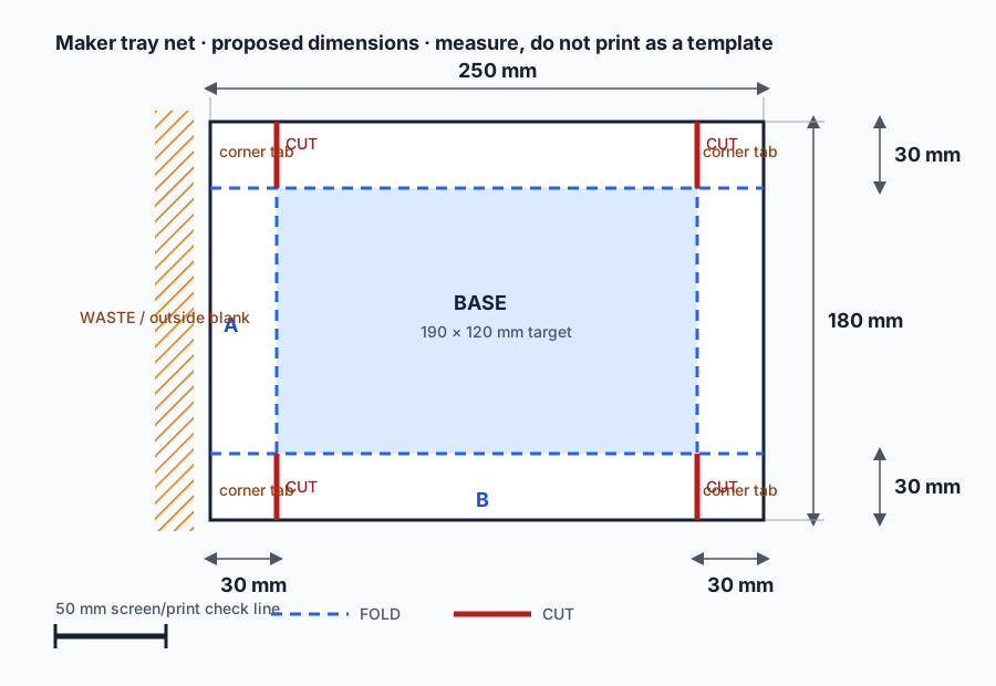
- a parts tray from a 250 × 180 mm blank with fold lines 30 mm from every edge.
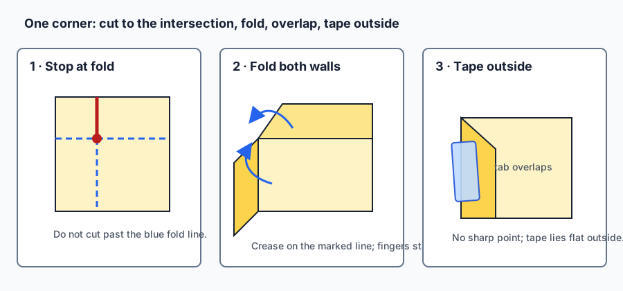
The proposed net leaves a target base of 190 × 120 mm and walls 30 mm high. Four cuts stop exactly where the fold lines cross. The walls fold up, the corner tabs overlap, and tape holds the overlaps from the outside.
Step-by-step build instructions
1. Prove the measuring process
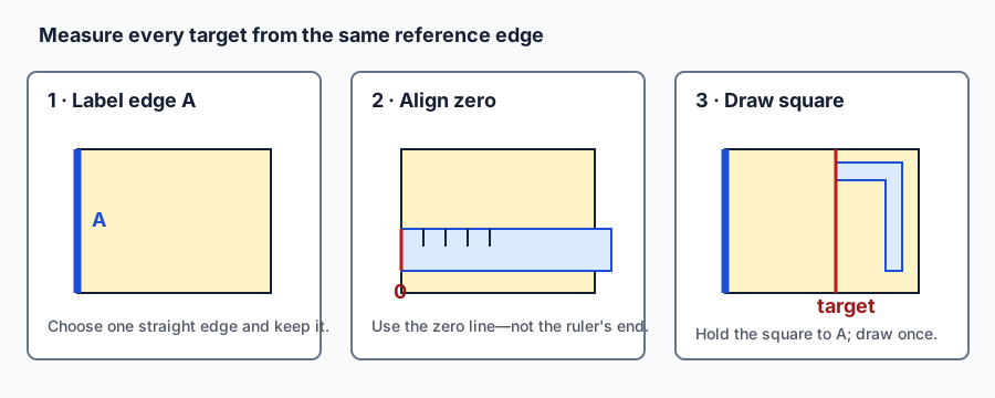
- Choose and label reference edges. Put the long blank flat. Choose a straight short edge as A and an adjacent long edge as B. Mark the letters near the edges without trimming them.
- Make the calibration part first. On the practice blank, label a straight edge A. Align the ruler's zero line—not its physical end—to A. Mark 100 mm. Use the square against A to draw the cut line. From the adjacent edge, mark and square a 30 mm width. Predict which measurement is more likely to drift, then cut the part safely.
- Measure the actual calibration part. Record target, actual, and difference for both dimensions. Difference is
actual − target; include+for long and−for short. If both are within 3 mm, mark “3 mm Maker Mark.” If not, circle the larger drift, name one likely cause—zero alignment, line placement, squareness, or cutting—and draw one corrected 100 mm line on scrap. Do not remake the whole part yet.
2. Lay out and build the tray
- Lay out the first tray fold from A. Align zero to edge A, mark 30 mm at two separated points, hold the square to A, and connect the marks. Verify 30 mm at both ends before moving on.
- Repeat using one coordinate system. Still measuring from A, mark the opposite fold line at 220 mm. Measuring from B, mark the near fold at 30 mm and the opposite fold at 150 mm. These paired coordinates should create a 190 × 120 mm base without switching to a new starting edge.
- Run the square-line checkpoint. Measure the distance between the two long fold lines at both ends; each target is 190 mm. Measure between the short fold lines on both sides; each target is 120 mm. If a pair differs, locate the drifting line before cutting.
- Mark the cut legend. Trace the four fold lines in a consistent dashed style. Mark four solid cut lines from the top and bottom outside edges along the two vertical fold lines, stopping at the first fold intersection. Put a small dot at each stop point.
- Make one demonstrated corner cut. The adult models one cut on scrap, or the learner makes the first project cut while the adult watches the stop point. Rotate the card for a safe direction. Stop at the dot. The learner repeats the other three cuts with a stop-point check before each one.
- Fold one wall at a time. Put the ruler on a fold line as a guide and lift the wall with fingertips; remove the ruler before pressing the crease. If the stock cracks, becomes sharp, or refuses a controlled fold, stop and record “incompatible stock.”
- Tape one demonstrated corner. Bring two walls upright. Let the square corner tab overlap the neighboring wall without forcing it. Apply one short strip of tape across the outside overlap and press it flat. Repeat for the other corners only after the first corner stands without a sharp point.
- Measure the actual base. Measure inside between opposite fold creases in both directions. Record target, actual, and difference. If either dimension is outside ±3 mm, do not hide it—mark which fold line created the drift.
Code
No code is required. Your repeatable “program” is the measurement sequence:
choose reference → align zero → mark target → draw square → verify → cut → measure actual
If the result drifts, change one step in that sequence rather than changing several things at once.
Make it work
Before adding a divider, the baseline tray should:
- rest on its base without a sharp exposed point;
- have four upright walls at least 25 mm high after folding;
- have all four corner cuts stop at fold intersections;
- hold 20 mixed, lightweight maker parts; and
- stay together when lifted 50 mm / 2 in and set down gently on a clear table.
If the tray misses a dimension but you can identify the specific drift and it passes the safe use test, keep it as evidence. A diagnosed miss is more useful than a hidden remake.
Understand it
A dimension is only meaningful when it has a starting point. If you measure one line from edge A, then measure the next distance from a slightly crooked line, each error can add to the next. A reference edge gives every related measurement the same origin.
A target is the planned value. An actual is what you measure after making the part. The proposed ±3 mm tolerance means a 190 mm target is provisionally acceptable from 187 to 193 mm. The tolerance is not permission to guess; it is a rule for interpreting evidence.
The square controls angle while the ruler controls distance. Using one without the other can place a line at the right distance at one end and the wrong distance at the other.
Change it
Design one divider for a named group of parts. This is the independent challenge; there is no single correct center-divider answer.
Desired outcome
One compartment holds a group you name—such as clips, washers, or card offcuts—without the divider collapsing during the 20-part use test.
Constraints
- Measure the tray's inside space where the divider will sit.
- Draw the divider before cutting it.
- Add two attachment tabs of your own design.
- Predict tight, sliding, or loose before the fit test.
- After the first fit test, revise at most one dimension.
- Do not copy a finished divider size from an adult or this page.
Prediction
In your notebook, write: “My divider target is ___ mm because the inside tray measurement is ___ mm. I predict the first fit will be ___.” Sketch the two tabs and label the dimension you are most uncertain about.
Hints
- Measure where the divider will actually touch, not the tray's outside.
- Decide whether the divider should touch both walls or leave a small clearance.
- If it is too wide, mark the amount of overlap before trimming. If it is loose, change the tabs or add a measured spacer rather than rebuilding the tray.
Parent guidance
Wait through ordinary crooked lines. Ask, “Which dimension can you check?” After about 7 minutes stuck, ask for the last known-good measurement. After 12 minutes without a test, require the learner to measure both the tray inside and divider actual width. Step in immediately only for unsafe cutting, resistant stock, or an incompatible material.
Debug it
Use the smallest test that separates likely causes.
| Symptom | Smallest useful test | Next controlled action |
|---|---|---|
| Base is the wrong size | Measure from A or B to each fold line | Correct or relabel the one drifting line |
| Opposite walls differ | Align their top edges and compare | Recheck the fold start and end points |
| Fold wanders | Measure both ends of the fold before refolding | Re-mark one square line; do not crease repeatedly |
| Corner opens | Test one clean taped overlap on scrap | Increase clean overlap or replace one tape strip |
| Tray rocks | Press each empty corner on a flat table | Identify the first high corner and inspect its fold |
| Divider buckles | Test it outside the tray | Change one unsupported height or add one fold |
Required diagnostic check
Point to edges A and B. Choose one failed or uncertain feature. State its target, measure its actual value, calculate the difference, and name the first step in the measurement sequence that could have caused that difference.
Project debugging guide
- Make the build safe and empty the tray.
- State the symptom without explaining it away.
- Return to the last known-good checkpoint.
- Measure at the first place behavior becomes wrong.
- Predict one likely cause.
- Change one variable only.
- Repeat the same test.
After 20 minutes without progress, stop the build. Save the parts, measurements, and two photos if appropriate; record whether the blocker is a missing item, defective item, incompatible size, unsafe tool, or unclear instruction.
Optional enhancements
Try this
Add a removable label for one compartment. It must not cover a sharp edge or interfere with the lift test.
Challenge
Add a second compartment with a different named purpose. Test whether 20 mixed parts still fit and can be retrieved without removing the divider.
Stretch
Design a fold-flat carrying flap that stays within the original card-and-tape material boundary. Test it open and closed ten times. The tray must still pass the baseline use test.
Recap
- A reference edge gives related measurements one stable origin.
- The ruler's zero line—not its physical end—starts the measurement.
- A square line controls angle.
- Target, actual, and difference turn “looks close” into evidence.
- A tolerance is a decision rule, not a substitute for measuring.
- Diagnosis comes before remaking.
Show what you learned
In your notebook, include:
- calibration target, actual, and difference for 100 mm and 30 mm;
- tray-base target, actual, and difference for 190 mm and 120 mm;
- a labeled divider sketch and fit prediction;
- the one variable changed after the divider test; and
- answers to: “What failed? Which measurement located it? Why did edge A matter?”
Demonstrate the 20-part lift-and-set-down test and point out the four safe corner joints.
What’s next
Keep the tray, calibration part, divider sketch, and measurement record. Later Level 1 Lessons will assume you can use reference edges, ruler zero, square lines, and target-versus-actual evidence. The next planned Lesson compares how corrugation direction changes the behavior of a card beam; its Family Pilot page will be linked only when its complete instructions pass the pilot gate.
Return to Level 1: Maker Foundations
Parent guide
What to prepare in advance
Inspect the work area, card, ruler, square, scissors, and tape using the Before you begin checks. Prepare only the outside rectangles the learner cannot cut safely. Do not draw project fold lines, pre-make a corner, or size the divider. Put missing or incompatible items on a list; do not purchase during this Lesson.
Where the child should work independently
The learner chooses A and B, performs the calibration measurement, lays out the fold coordinates, repeats three corner cuts after one demonstration, records actual dimensions, designs the divider and tabs, predicts fit, and decides which one dimension to revise.
Moments when the parent should resist taking over
Do not redraw an ordinary crooked line, center the divider, make the corner visually neat, erase an out-of-tolerance result, or suggest the final divider size. Ask for target, actual, difference, and the last known-good checkpoint.
When the parent should step in
Stop immediately for a hidden staple, sharp point, unsafe cutting direction, forced scissors, resistant or cracking stock, or a frustrated learner moving too quickly to stay safe. At 7 minutes stuck, ask a diagnostic question; at 12 minutes without a test, require one measurement; at 20 minutes without progress, end the build and record the blocker.
A simple understanding-based assessment
The Lesson is successful when the learner can use the reference-edge sequence with decreasing support, record honest target/actual evidence, diagnose one drift, complete or safely stop the baseline tray, and own the divider prediction and controlled revision. Neatness and an automatic ±3 mm pass are not required. Please report the pilot result or unclear instruction without including a child's name, face, or private information.